Every day, foundries are faced with loss of knowledge due to the retirement of experienced operators and the difficulty of replacing them with new talent, An automated pouring system – requiring very little operator intervention – is needed now more than ever. Based on the experiences with automation and the active use of the collected information in its data base pour-tech AB, Sävedalen, Sweden, has created a solution for artificial intelligence called EASYpour™.
At first a number of challenges were identified by the development team, as the process conditions are continuously changing due to, among other things:
- Imperfect molds
- Slag in the liquid iron
- Bath level variations
- Temperature changes.
While aiming for minimal operator interference, the team was also focusing on improving the casting quality and increasing the line productivity. In this context it had the values for its customers in focus, so for example:
- Less manual work
- Allowing the operator to focus more on quality checks, preparation of further batches, taking samples etc.
- Increased product quality due to continuous improvements by the developed algorithm
- Shorter line cycle times
- Less production costs
- Continuous logging of the pouring quality, evaluated in real time and associated with each individual castings in order to ensure traceability.
The development of the algorithm was one part of the task, the other part was finding the right selection of processes needed for the reliable operation of EASYpour™.
Suitable foundry systems
The following vessels and devices, in combination with stopper and nozzles are state of the art pouring units:
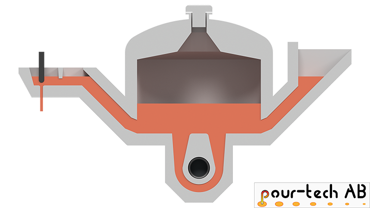
Figure 2: Channel type furnace 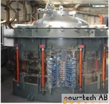
- Unheated pouring ladles are, because of their flexibility and many other advantages, used in a great number of foundries worldwide.
- Channel type furnaces (Figure 2) for the production with single grades of iron – with only small chemistry variations. A complete change of iron grade is of course possible, but laborious and time consuming. If covered with inert gas, ading of Magnesia will be reduced.
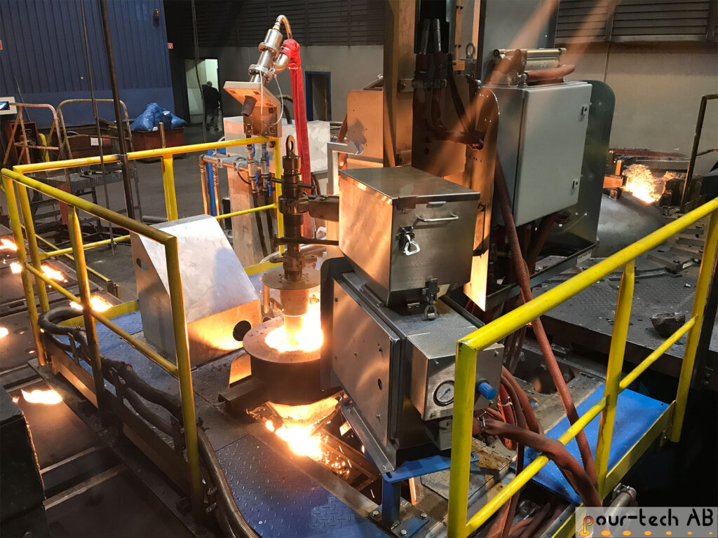
- Coreless press pour systems (Figure 3) known for high flexibility and less time-consuming iron grade changes, exact control of pouring temperature and the resistance to thermal shocks. If covered with inert gas, fading of Magnesia will be reduced.
- Foundry specific pouring units designed inhouse using stopper rods and nozzles (Figure 4).
Unheated pouring vessels
Compared to pouring furnaces, unheated pouring systems (Figure 5) are lower in weight and can therefore be equipped with pancake load cells to monitor the liquid iron content inside the ladle. Unheated bottom pour solutions are common for continuous and steady production where stable refilling of the vessel is possible.
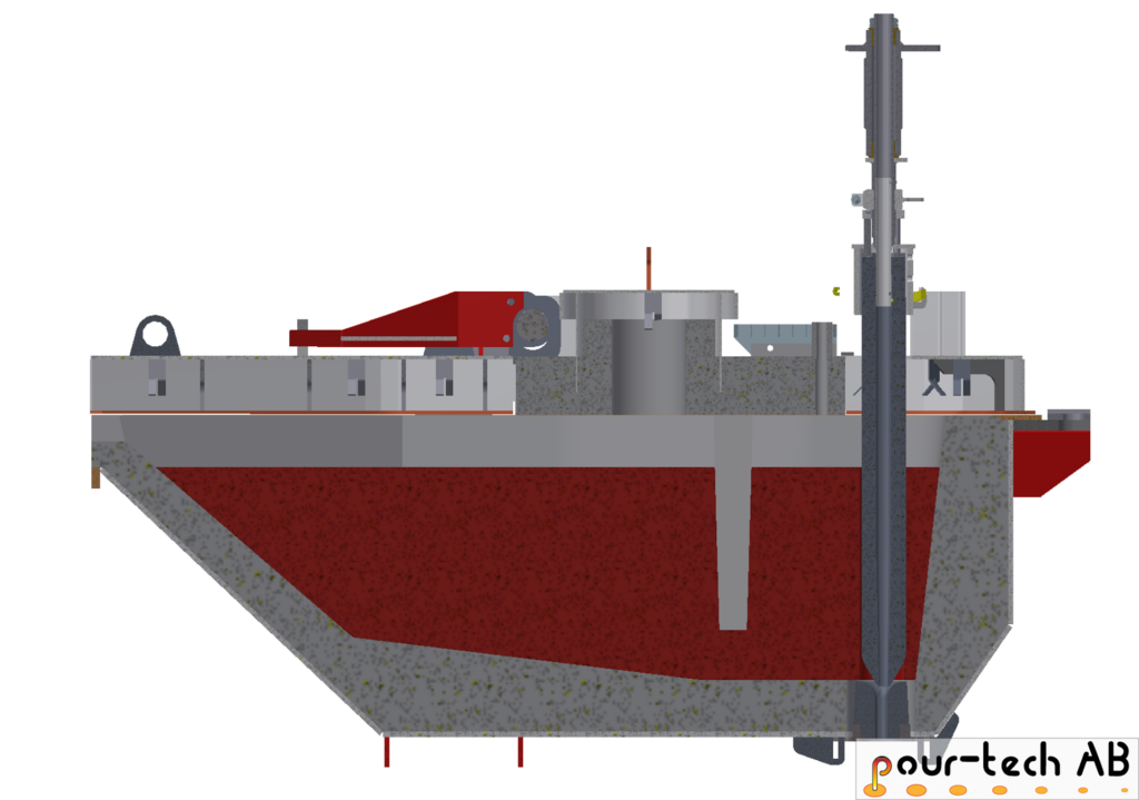
Compared to pouring furnaces, unheated pouring systems (Figure 5) are lower in weight and can therefore be equipped with pancake load cells to monitor the liquid iron content inside the ladle. Unheated bottom pour solutions are common for continuous and steady production where stable refilling of the vessel is possible.
Figure 5: Unheated vessel
A constant flow rate of iron is provided thanks to a special software, which compensates for the changing ferrostatic pressure by adjusting the pouring parameters, also in the case of a fast-rising iron level during refill.
A slag dam in the center of the pouring vessel is separating the filling from the pouring section. Because of its lower specific density, the slag will float up and the dam keeps it in the filling section, while the clean melt flows under the dam into the pouring section, reducing filling turbulence.
Compared to pouring with a hand ladle, which is still very common, the risk of slag entering the mold is very much reduced. At the same time, the yield can be improved, since the required pour cup is only 2.5 times the size of the pouring nozzle and all metal that is transferred to the vessel can be poured (no remaining heel as in a hand ladle).
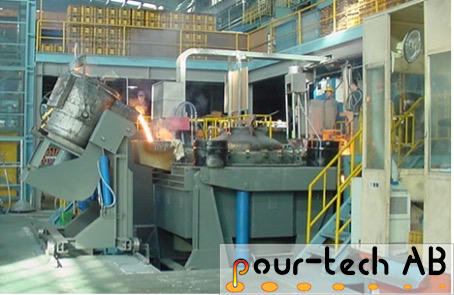
The system is designed for a short residence time of the liquid iron in the vessel. This has a very beneficial effect on iron alloy changes and the production of nodular iron castings. The pouring vessel is designed so that 70 % of the content is poured off within seven to ten minutes. Conversely, the tub is refilled six to eight times an hour. This allows the temperature loss and the Mg fading to be controlled in a targeted manner. The pouring vessel can be refilled manually or automatically with a skip-system (Figure 6).
An order is currently being processed on an automatic tight flask line. A transport ladle hangs on an automatic crane and transports the ladle, filled at the melt shop, to the treatment and later to the deslagging station. The transfer ladle is then placed on such a skip and locked in. One operator per shift is expected for the entire process, including pouring.
FORCEpour system
Especially with vertically parted molding lines, the cycle time is mainly determined by the pour time, even with moderate pour weights. In order to fully utilize the stoppage time of the mold string for the pouring process, the optimization by FORCEpour was developed.
With FORCEpour, the stopper starts to open while the mold string is still in motion, as soon as the pouring cup reaches the pouring zone and the outermost edge of the cup is recognized by the upstream positioning laser. The pour is therefore started before the end of the index, and timed such that the first iron just hits the pour cup.
This allows a few tenths of a second to be saved with every single cycle. For a molding line operating at 500 molds per hour, each 0.1 second of pre-start generates 7 more molds per hour. A vertical molding line at a French foundry is currently producing 580 molds per hour with a laser based pouring system featuring FORCEpour. FORCEpour is an addition tool for optimizing the process, especially in connection with artificial intelligence.
Pouring temperature
The verifiable pouring temperature for each individual mold is important for quality control. This is why the temperature is measured with a pyrometer as it exits the pouring nozzle and is recorded in the data base.
To calibrate the pyrometer, it is necessary to measure the iron temperature in the furnace spout or ladle from time to time with a dip lance. With the dip lance reading directly integrated into the database, the pyrometer can be automatically calibrated. If the dip lance is not integrated into the system, the measured temperature can beentered into the system via the Operator’s Panel.
InoTECH inoculation system
For EASYpour™ the instream inoculation is not primary necessary, but for the casting quality it is a significant requirement. Like the pouring process, the instream inoculation is part of the quality control measures. Therefore, all relevant inoculation information for each mold is stored in the data base. The inoTECH inoculation unit is known for:
- High Uptime
- Multiple sensors for reliable operation
- Easy installation
- Easy and fast calibration
- The possibility to operate with double feeder systems
The InoTECH inoculation unit is working with removable hoppers for capacities of 25 or 50 kg, a powder grain size of up to 0.8 mm and a density of approx. 1.7 kg/dm3. Feeding rates between 1-60 gram/sec are available. The amount of inoculant delivered is recorded in the database. But does this amount really correspond to the amount that hits the iron stream – considering that often, there is a significant layer of inoculant in the surface of the mold?
This material is wasted, as it doesn‘t enter the casting, and if this inoculant is not removed from the mold, it will also compromize the quality of the green sand and the surface finish of the casting. The newly developed system uses a laser to provide a light curtain between the inoculation feed tube and the iron stream and enables a camera to detect the individual inoculant grains that hits vs. misses the iron stream counting them in real time to determine a hitrate. The hit rate of the inoculation is further optimized by the feed tube which automatically corrects its aim, in the event of a fluctuating iron stream.
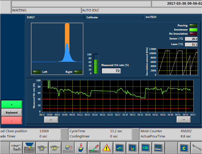
The HMI screen (Figure 7) shows all the significant information, including the distribution curve of the inoculant vs. the pouring stream. In addition, the inoculation hit rate is shown. These values are also documented in the database and made available for the quality management.
At this point a few words about the iron stream exiting the nozzle: This stream is not always compact and sometimes breaks up into several streams, which makes it difficult to control the level in the pouring cup pure vision and single point observations. The line laser used as standard for measuring the level of iron in the pouring cup consists of the equivalent of one million laser points, which are viewed by a pouring camera. However, only one thousand “laser points“ are sufficient for a stable pouring process. There is no doubt that the 0.1% of all laser points required for the process will capture the filling level in the cup.
Artificial Intelligence
Data base
Ever since pour-tech was founded back in 2011, the databases have been an important part of the companys knowhow. As mentioned in a previous chapter, one of the necessary accessories for a powerful artificial intelligence was the integration with a powerful database. The pourTECH Data Base (PTDB) has the following functions:
- Storage of all available pouring and production data in a secure database
- Dual raided HD
- SQL data base
- Basic report tool via a standard web browser such as Google Chrome
- No extra programs are needed
- PTDB keeps data for >5 years of production
- Possibility to import data from other foundry equipment – to be stored in the PTDB A selection of standard production reports are available, and reports tailored to specific customer needs are easy to create. The data presented are certainly not new and have been part of the applications of IoT for a long time, but all this data also forms the basis for the next logical steps to develop the next level – to create artificial intelligence.
A selection of standard production reports are available, and reports tailored to specific customer needs are easy to create. The data presented are certainly not new and have been part of the applications of IoT for a long time, but all this data also forms the basis for the next logical steps to develop the next level – to create artificial intelligence.
System modules
Figure 8 shows the summary of all tools and devices described so far, these are:
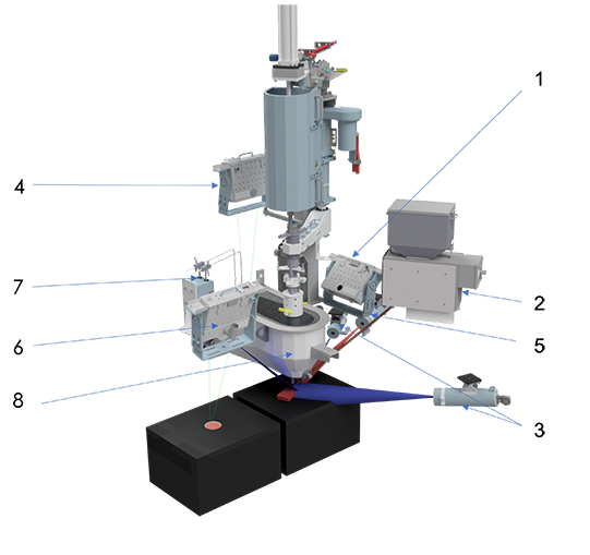
- spot laser for positioning and line laser for constant filling processinoTECH inoculation device with self-adjustable feeding tube
- inoTECH inoculation device with self-adjustable feeding tube
- inoTECH-camera and light-curtain laser for counting inoculation grains
- spout level laser, providing level feedback to the furnace pressure system
- pyrometer to provide pouring temperature for each pour
- final level laser for optimizing the final iron level, checked at a position downstream from the pouring station
- safety electrodes for emergency depressurization
- optimized pouring spout; the distance to upper edge of the mold is approx. 165 mm
Figure 8: Summary of basic devices to create an AI system
The complete integrated package is available for both heated and unheated pouring systems. EASYpour™ can be retrofitted to existing systems from pour-tech by installing a final level laser and the PTDB.
Production with EASYpour™
The internet of things collects the data and the artificial intelligence evaluates the context and gives recommendations for actions with EASYpour™. At an advanced level, the AI executes its calculated recommendations autonomously.
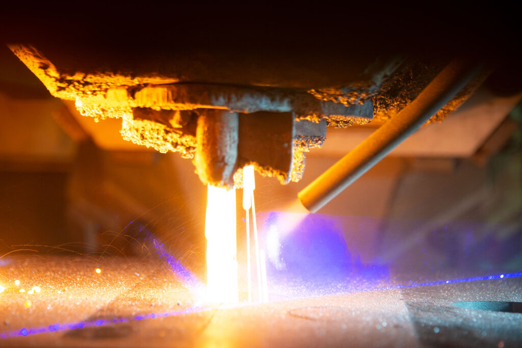
Figure 9 shows the line laser that monitors the filling of the mold. Together with the spot laser for positioning, this laser combination has been in use in this foundry for over a decade. A final level laser monitors the poured level of iron two molds downstream from the pouring. The final level laser (features blue light) represents the next generation in laser technology and was installed together with the EASYpour™ solution. The blue laser technology is less sensitive to high temperature and has a longer lifetime than older (green) lasers.
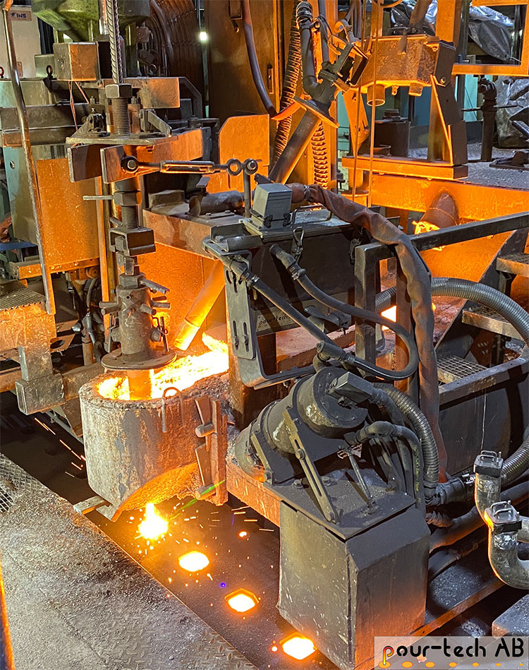
In the upper area of figure 9 the spout level laser in the siphon of the furnace is seen. To the left of it is the plunger system used to clean the stopper and nozzle from slag during the production of CGI and Nodular iron. If pouring must take place automatically with the laser control, but without EASYpour™, thirteen numerical parameters must be entered and saved in the PLC for each new set of patterns.
Easy Interfaceuse with EASYpour™
Figure 10 shows the HMI screen for the EASYpour™-solution. Only three numerical parameters need to be entered at the beginning of the first production cycle of a new pattern. These parameters are shown in the centre of the image:
- Stopperoffset
- TT( Total Time / Pouring time)
- Desired metal level in the cup

Every time the system learns independently of the operator in order to optimize itself, the green Learning bar in the top right of the picture moves up. After the first pouring cycle of a new pattern has been completed, the Stopper offset and TT are included in the optimization together with the other parameters. The green bars above and below the two parameters light up during optimization and show the direction and intensity of the action. Two graphs are placed on the left of the screen. The upper graph shows the (green) calculated iron level, which is necessary for a clean filling of the pouring cup. The actual filling level, which results from the reaction of the stopper, is shown by the yellow line. The two thicker red lines at 66 and 100 represent the lower and upper boundaries of the pouring cup. The “Level” parameter was set 96. This means the desired fill level is 4 mm below the top of the mold (as the top of mold is defined as 100). The opening of the stopper is shown in the lower graph. In this case, the stopper opens up to the selected maximum distance of 12 mm between the nozzle and the tip of the stopper. At the beginning the pouring, the stopper is opened up at maximum speed up to the limit, for the fastest possible filling of the pouring cup. This is intended to prevent ambient air from being sucked into the gating system, causing oxide formation.
The maximum speed of the stopper movement is about 100 mm per second. The maximum flow rate of iron is reached when the stopper is lifted about 30 millimeters from the nozzle. Thus, the stopper reacts very quickly, opening in a few tenths of a second. The pouring time and the flow rate are adapted to provide a smooth and repeatable mold filling thanks to the precise laser measurement.

