Energy costs and their reduction in the foundry process have been the dominant issues in our industry for years. Around 80% of this energy is used in the area of melting and holding the temperature of molten metal. More and more efficient melting technologies have been used in the melting shops in recent years, so that nowadays marginal reductions are expected.
With the project of the wholistic simulation of the unheated, laser-controlled bottom stopper pouring, further potential for energy savings should be discovered. The term ‘wholistic’ considers the process from the targeted refilling of the molten metal in the pouring vessel to the filling of the mold via the pouring cup into the down sprue of the gating system.
Another important issue in the project was the actual secret of the foundries to produce high-quality castings with the lowest scrap rate: the constant process conditions. Only those who produce continuously under constant process conditions can also expect high-quality products.

For many years, only two casting processes were known on green sand mold lines:
- Discontinuous ladle pouring with the necessary large pouring cups, residual amounts of iron remaining in the ladle at the end of the pouring cycle and ladle changing times that are missing for production.
- Stopper pouring in channel induction furnaces, which are heated 24 hours a day and metal grade changes consume a lot of time because of the large sump.
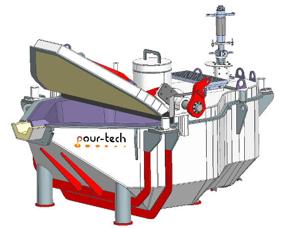
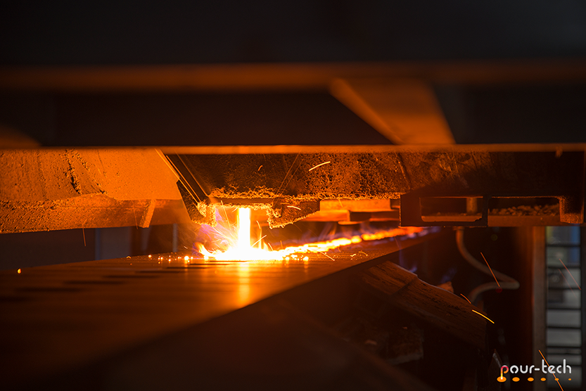
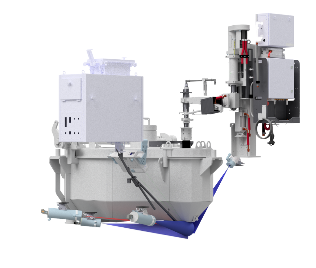
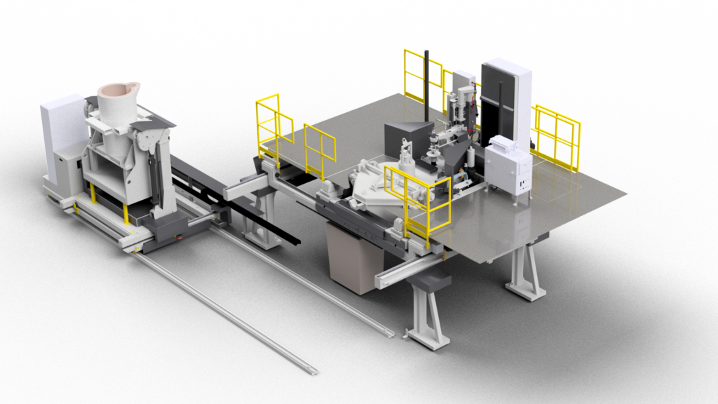
To find a way around the complications and increase flexibility, pour-tech AB has created a pouring technology that combines the best of both: the unheated stopper pouring device with instream temperature measurement, inoculation and an artificial intelligence-controlled pouring process (fig. 3).
Efficiency in focus
The process is ideal for continuous pouring with a uniform bath level in the pouring cup of up to 600 molds per hour on vertical parted mold lines (fig. 2), as well as more complex pouring parameters on large, slower running horizontal parted mold lines. With regular recharging according to pour-tech AB guidelines for the pouring vessel, the temperature losses can be kept constant at under 2K loss per minute. In the past eleven years, the pouring process has been continuously developed by pour-tech AB and is becoming more and more popular worldwide. One of the reasons for the success are greatly reduced carbon footprint, reduced manpower, higher yield, the avoidance of holding energy and reduced repairs to the refractory lining.
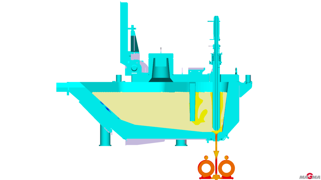
The system itself has robust steel construction and hydraulics, stable laser technology and comprehensible control technology. Now it was time to take this leading technology to a new level through further development. The basics about the unheated pouring process were worked out together with the specialists from M5 Engineering (Thailand) Co. Ltd. Their expertise in process optimization has now contributed to the optimization of the process through extensive simulations. The temperature distribution and turbulence during pouring of the molds and the recharging of melt into the pouring vessel, but also for laminar pouring via stopper and nozzle, were explained and improved (fig. 4).
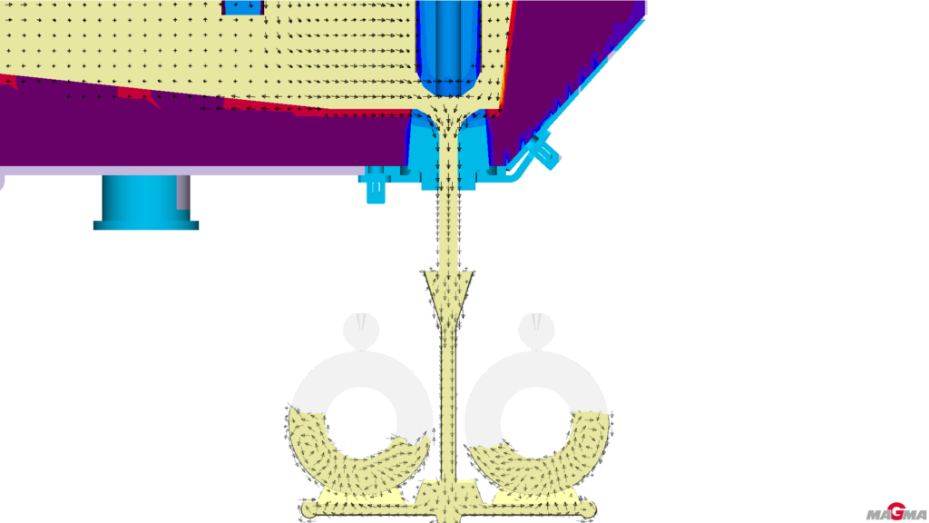
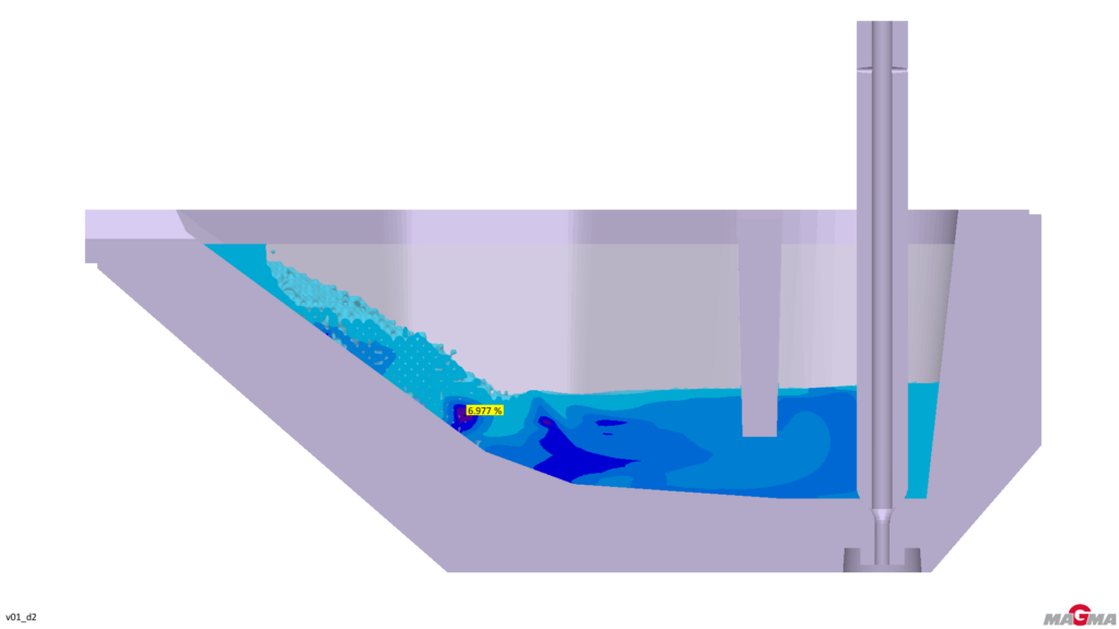
Based on intensive preliminary discussions between pour-tech AB and M5 Engineering (Thailand) Co. Ltd. on technical questions, the first simulations were carried out. They showed the optimization potential for various topics that had not been thought of, which were also tackled immediately. This included the optimization of the refractory lining of the pouring vessel in the inlet for low-turbulence recharging and thus the reduction of the air entrapment of the melt in the otherwise closed pouring device. As a result, the angle at which the molten metal hits the lining was optimized and the air entrapment was reduced to below 10% of the initial value (fig. 5). An automatic skip system to empty transfer ladles was designed for this, which ensures a defined and constant refilling process. The first of these systems are already in operation.
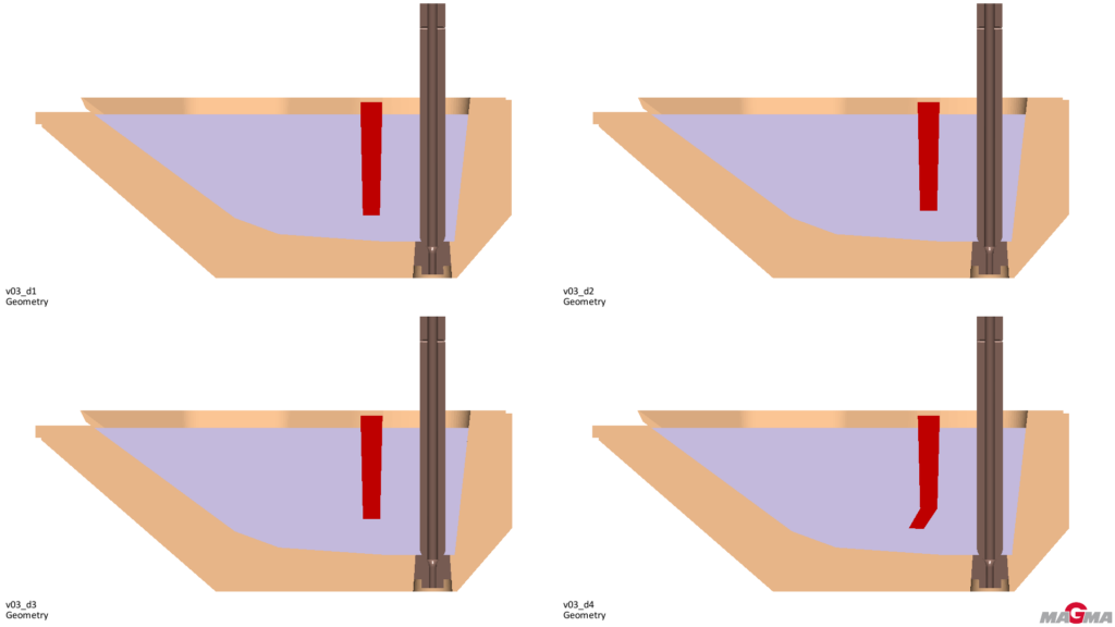
Another major topic was the design of the slag weir to prevent process slag in the area around the stopper
This slag weir extends the service life of the stopper and nozzle but ensures at the same time no slag particles are poured (fig. 6). As important as this slag weir is to keep clean melt and stopper and nozzle, when changing alloys, it increases the time for fresh molten metal of the new alloy and the previous alloy to mix in the heal of the vessel.
In order to optimize all requirements in relation to each other, several designs of a new slag weir were drawn and the process was simulated with these new variants. These comparisons also brought new and unexpected results, which also gave valuable information for future developments. In this way, the heal in the vessel could be reduced by more than 25%. About six seconds after the start of recharging, the fresh molten metal has reached the area of the stopper and nozzle. The mixing takes place very quickly. As a result, an alloy change can be carried out by over-treatment of the fresh molt in many cases without first emptying the vessel.
Ultimately, a design was found that increases flexibility for foundries while reducing production costs. At the same time, the laminar exit of the molten metal from the pouring nozzle during mold filling could be verified. For foundries, there is sometimes an ROI of just six months using this pouring device.
Summary
With more than 30 years of experience and over 500 installed systems for pouring iron-based alloys, pour-tech AB has become the leading supplier of automatic pouring equipment (fig. 7). Through intensive cooperation with M5/MAGMASOFT the basic knowledge of the process could be deepened and new conclusions from simulations could be summarized. In this way, constructive detail changes could be made, which reduce possible sources of error. A casting defect always arises from the sum of a large number of parameters that lie outside the respective process window. The changes made will thus reduce the bundle of these possible sources and casting failures and facilitate troubleshooting in the operational process.
Written by:
Michael Colditz Sävedalen, Sweden
Loedwilat Thipramongkhon, Bangkok, Thailand
Chindanai Challinak, Bangkok, Thailand